As Alice departed from the stele, the prophet’s voice drifted faintly from deep within the corridor:
“Remember that blueprint. Between ideal and reality lies a stretch of RF front-end.”
Alice did not look back. Ahead, the luminous corridor began to branch—not into pure-white streams of code, but into a hallway lined with schematic diagrams on both sides. Each wall segment illustrated one stage of a signal flow diagram, like a textbook torn open and laid across the walls.
She paused at the first wall segment.
The wall displayed a complete signal flow diagram—from antenna ① on the far left to antenna ② on the far right—connected by glowing arrows through each functional block:
Antenna ① → RF Front-End → ADC → DDC → Baseband Processing → DUC → DAC → RF Front-End → Antenna ②
Beneath the diagram ran a line of small text:
“This is the body of an SDR—signals flow left-to-right for reception, right-to-left for transmission.”
Alice read left to right, then right to left. She saw signals enter via antenna, pass through the RF front-end, become digital via ADC, slow down via DDC, undergo ‘thinking’ in baseband processing, then reverse through DUC (up-conversion), DAC (back to analog), RF front-end (amplification), and finally transmit via antenna.

“The RF front-end is both the first and last stage on this path—it receives the signal first upon entry and bids farewell last upon exit.”
“What exactly does this part do?” Alice murmured to herself.
She walked forward a short distance, and the second wall segment provided the answer.
I. Three Functions of the RF Front-End
The second wall depicted an enlarged ‘RF Front-End’ module—broken down into three cascaded submodules, each marked with distinct colored light:
① Low-Noise Amplifier (LNA) → ② Filter → ③ Frequency Converter (Mixer)
“The RF front-end performs three functions,” the wall text stated, “and only three.”
Alice paused to read carefully:
First: Amplification.Signals arriving from the antenna are extremely weak—perhaps only one microvolt. Direct processing would drown them in noise. The RF front-end first amplifies the signal using aLow-Noise Amplifier (LNA)The key is ‘low-noise’—the amplifier itself must introduce minimal additional noise; otherwise, it amplifies its own flaws along with the signal.
Second: Filtering.The antenna receives more than just your desired frequency—it captures all electromagnetic waves across the entire band. The RF front-end uses aBandpass Filterto cut away unwanted frequencies, retaining only the band of interest. Like covering your ears to block drums and applause while listening solely to the violin.
Third: Frequency Conversion.This is the most critical step. Signals received by the antenna areHigh-Frequency Signals—tens, hundreds, or even thousands of megahertz. High-frequency signals travel fast, have short wavelengths, and carry high information density—but they’re difficult to digitize directly with an ADC. ADCs lack sufficient speed, and even if fast enough, lack required precision. So the high-frequency signal must be ‘converted’ to a lower, more manageable frequency.
“There are two methods for this ‘conversion’,” the wall text continued, “just as there are two approaches to translation.”
II. Two Frequency Conversion Architectures: Superheterodyne and Zero-IF
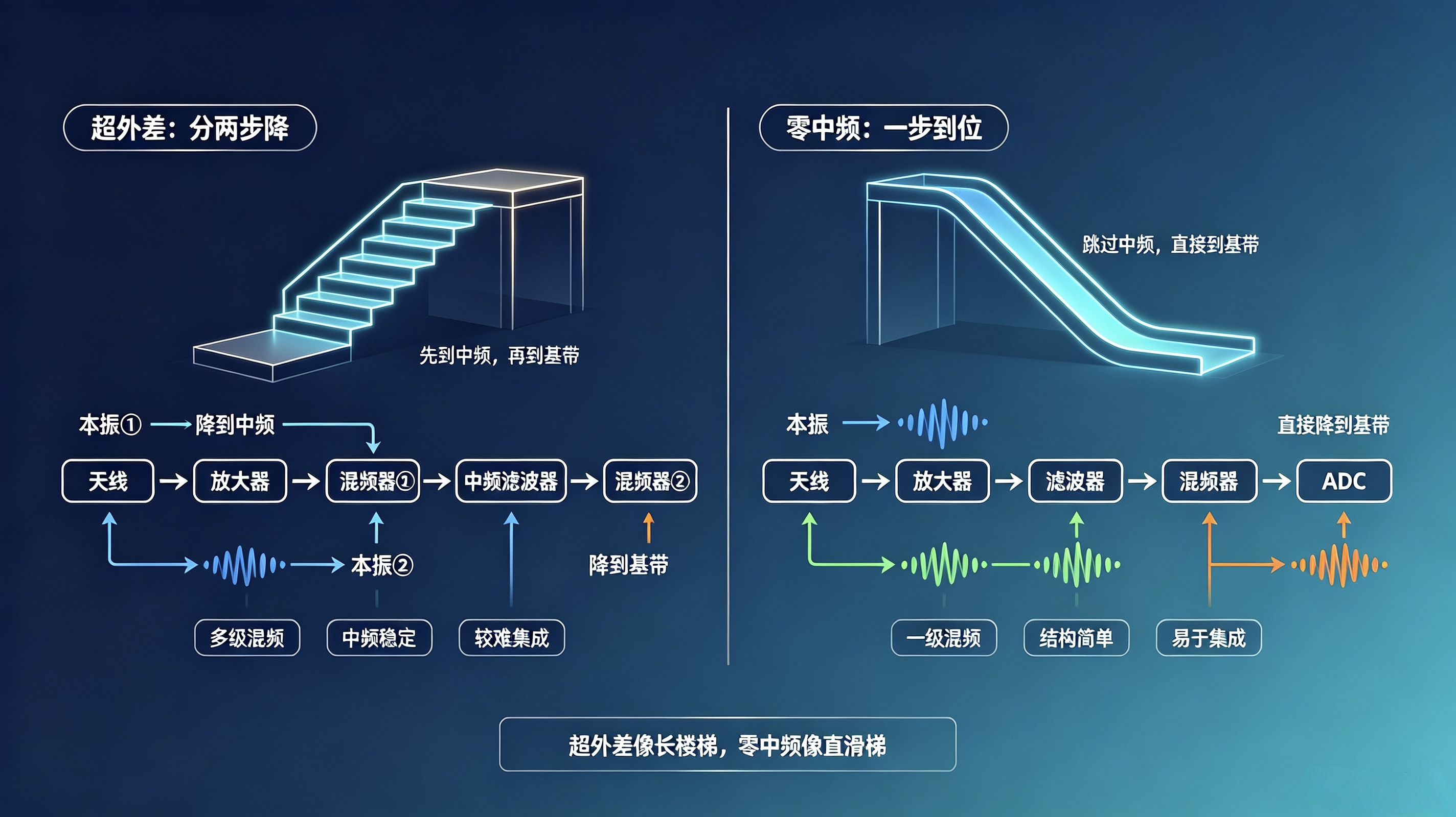
Two side-by-side schematic diagrams appeared on the wall.
Left Diagram: Superheterodyne Architecture

Signal enters from antenna → Amplifier → Filter →Mixer ① (mixed with Local Oscillator to convert to Intermediate Frequency)→ IF Filter →Mixer ② (mixed with another Local Oscillator to convert to Baseband) → ADC
“Superheterodyne: Two-step down-conversion.First, the high-frequency signal is converted to an ‘Intermediate Frequency’ (IF), then from IF to baseband. IF is a fixed intermediate frequency—whether the input is 2 GHz or 900 MHz, the superheterodyne architecture first converts it uniformly to the same IF (e.g., 70 MHz), then down-converts once more to baseband.
“Advantages of superheterodyne:Mature, stable IF processing; excellent filter performance.Disadvantages:Requires multiple mixing stages; complex circuitry; needs external surface-acoustic-wave (SAW) filters; difficult to integrate. ”
Alice recalled the ‘soldered rooms’ she’d seen during her first adventure—the IF transformers built with copper coils and capacitors inside vintage radios were products of the superheterodyne architecture.
Right Diagram: Zero-IF Architecture
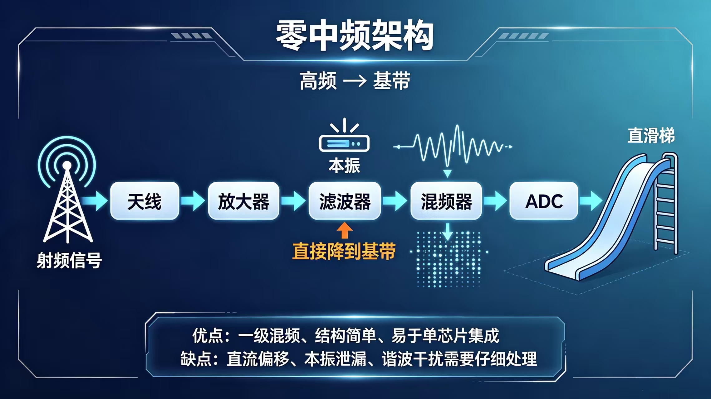
Signal enters from antenna → Amplifier → Filter →Mixer (mixed with Local Oscillator for direct conversion to Baseband) → ADC
“Zero-IF: One-step conversion.A single local oscillator directly converts the RF signal to baseband—skipping the IF stage entirely. Because no IF exists, it’s called ‘zero-IF’.
“Advantages of zero-IF:Only one mixing stage; simple circuitry; integrable onto a single chip.Disadvantages:DC offset, local oscillator leakage, harmonic interferenceand other issues require careful mitigation.。”
Alice studied the two diagrams repeatedly. Superheterodyne resembled a long staircase—first descending to an intermediate landing, then one more step to ground level. Zero-IF resembled a straight slide—launching from the top floor directly to the bottom.
III. RF Integrated Transceivers—the ‘Heart’ of Zero-IF
The next section of wall text accompanied an enlarged chip schematic:
“Modern SDR platforms—especially compact USB dongles and boards—almost universally adoptZero-IF Architecture. The reason is simple: the entire RF front-end can be integrated onto a single chip—amplification, filtering, mixing, and even ADC—all in one.”
The wall listed several representative RF transceiver chips:
AD9361 (Analog Devices): The most renowned chip in the SDR domain. Covers 70 MHz to 6 GHz, with tunable bandwidth from 200 kHz to 56 MHz. 2×2 MIMO((dual transmit/dual receive). Used in USRP B200/B210.
AD9371: An upgraded version of AD9361. Frequency range 300 MHz to 6 GHz, higher bandwidth, and more integrated digital signal processing functions—used in higher-performance SDR platforms.
LMS7002M (Lime Microsystems): Covers 100 kHz to 3.8 GHz, maximum bandwidth 120 MHz。Core chip of the LimeSDR series—a hallmark of the open-hardware community.
GC080X (GeChip Technology): A domestic wideband RF transceiver chip, 30 MHz to 6 GHz, 100 MHz bandwidth. Supports 2T2R. Often paired with domestic FPGAs.
CX9261H (Chengxin Technology): A domestic high-performance RF transceiver, 70 MHz to 2700 MHz, 3Rx/2Tx, primarily used in military and high-end communication systems.
“These chips are the ‘heart’ of zero-IF architecture,” concluded the wall text, “compressing what once required an entire circuit board into something smaller than a fingernail. The RF front-end is no longer a ‘soldered room’—it has become a programmable, reconfigurable chip. Different frequencies, bandwidths, and gains are all set via software.”
Alice gazed at the schematic illustrations of those chips—each differing in size and shape, yet all performing the same task: converting antenna signals to baseband (or vice versa).
“So…” she said slowly, “the RF front-end has also shifted from ‘hardware-soldered’ to ‘software-configurable’?”
The wall text flickered—as if in agreement:
“Yes. The RF front-end is no longer a fixed circuit. Filter bandwidths, mixer frequencies, and gain settings of these chips are all configurable via software writes to registers. The ‘hardware boundary’ of the RF front-end continues receding, with more and more functionality being taken over by software. ”
IV. ADC—the Gateway to the Digital World
She continued walking down the corridor. The next wall displayed an ADC schematic—a circular, blue-glowing ‘gateway’, where signals entered from the left (analog world) and exited to the right (digital world) as orderly strings of 0s and 1s.
The wall text was concise:
“ADC—Analog-to-Digital Converter. Where analog signals become digital signals.At this stage, the signal is no longer a continuously varying voltage, but a sequence of samples—each sample represented by a number.”
“Sampling Rate: How many times per second sampling occurs. Higher rates enable handling of higher-frequency signals. CD audio uses 44.1 kHz; human voice, 8 kHz; Wi-Fi requires tens of MHz.
“Resolution: How many bits represent each sample. More bits mean higher precision. CD audio uses 16 bits; professional SDRs use 12-bit, 14-bit, or even 16-bit ADCs.
“The ADC is the throat of an SDR—it determines the highest frequency and finest precision the SDR can handle. Higher ADC sampling rate and resolution yield wider ‘field of view’ and sharper clarity—but also increase power consumption and cost.”
Alice recalled the prophet’s words: “ADCs aren’t fast or precise enough yet. The ideal is direct ADC after the antenna—but reality demands digitization at IF.” What she now saw was that ‘reality’—the signal arrives at the ADC gate only after passing through the RF front-end’s three stages.
And the ADC’s output marks the starting point of the digital signal’s journey—the next destination awaiting exploration.
V. Transmission Path—Traversing in Reverse
She reached a junction in the corridor, where a sign read:
“Reception path completed. Transmission path is the reverse mirror image.”
Alice turned around to look back.
If the reception path is:Antenna → RF Front-End (amplify/filter/down-convert) → ADC → DDC → Baseband Processing
then the transmission path is its mirror:Baseband Processing → DUC → DAC → RF Front-End (up-convert/filter/amplify) → Antenna
“Reception converts high frequency to low; transmission converts low frequency to high,” the wall text explained. “The RF front-end performs the exact opposite tasks in transmission versus reception—it up-converts baseband signals to RF frequencies, then amplifies and transmits them.”
She continued walking—and found herself circling back to the location of the first wall’s full signal flow diagram.
A new line of small text now appeared beneath the diagram—previously absent:
“Each stage of the signal flow unfolds into its own dedicated space. You’ve just traversed the RF front-end. You’ve now met the ADC.”
“Next, you’ll explore the segment immediately after ADC and before baseband processing—the Digital Frequency Conversion Factory.”
“But before that,” the wall’s light suddenly parted left and right, revealing a new corridor, “you must first meet the three protagonists who make this path operate. They are already ready.”
Alice turned toward the new corridor. At its end glowed interwoven red, blue, and green light—red vibrant, blue profound, green steady—three beams converging from the same direction into a path leading into the unknown.

She walked toward that tricolor light.
(To be continued. Next chapter: The Stage of the Three Brothers—Alice will enter a grand theater to witness FPGA, DSP, and CPU performing together, each fulfilling their distinct role. Before entering the Digital Frequency Conversion Factory, she must learn: Who performs frequency conversion? Who handles computation? Who oversees the whole system?)
[Chapter 3 Knowledge Recap]
| SDR Concept | Fairy-Tale Embodiment |
| Complete SDR Signal Flow | Antenna → RF Front-End → ADC → DDC → Baseband Processing → DUC → DAC → RF Front-End → Antenna—The book’s ‘map’ |
| Three Functions of RF Front-End | Low-Noise Amplification (LNA), Bandpass Filtering, Frequency Conversion—preparing the signal for digitization |
| Low-Noise Amplifier (LNA) | Amplifies weak signals without introducing significant new noise |
| Bandpass Filter | Cuts away unwanted frequency bands, retaining only the desired band |
| Superheterodyne Architecture | Two-step down-conversion: RF → IF → Baseband; complex circuitry but stable performance |
| Zero-IF Architecture | One-step conversion: RF → Baseband; simple, integrable—mainstream in modern SDRs |
| RF Integrated Transceivers | AD9361 (USRP), LMS7002M (LimeSDR), GC080X, CX9261H—compressing the entire RF front-end into a single chip |
| ADC (Analog-to-Digital Converter) | The ‘gateway’ between analog and digital worlds—sampling rate and resolution define the SDR’s capability ceiling |
| Transmission Path Mirrors Reception | Reception down-converts; transmission up-converts—the RF front-end traversed in reverse |
Preview of Next Chapter: The Stage of the Three Brothers—Alice will enter a grand theater to see FPGA, DSP, and CPU perform together, each playing their part. She’ll understand SDR’s digital-domain division of labor: heavy lifting to FPGA, precision work to DSP, overall control to CPU.
This article is original content. Please credit the author, official WeChat account, and official website (https://www.dyaotech.com), and unauthorized modification or commercial use is strictly prohibited. Violators will be held accountable!