
On February 24, 2026, National Instruments (NI) published the USRP Selection Technical White Paper on its official website. Original link: https://www.ni.com/zh-cn/shop/wireless-design-test/what-is-a-usrp-software-defined-radio/which-usrp-is-right-for-you.html. This white paper systematically explains the USRP hardware architecture, selection criteria, software development compatibility, and technical specifications of each model. It provides engineers working in communications, radar, electronic warfare (EW), and 6G R&D with a practical, application-driven basis for selecting appropriate USRP devices. Additionally, it offers professional guidance for selecting Software-Defined Radio (SDR) equipment used in military RF technology research, testing, and deployment.
Preface
Software-Defined Radio (SDR) centers on software-defined RF functionality, breaking free from the inflexibility of traditional hardware radios. With advantages including flexible configurability, scalable functionality, and low development barriers, SDR has become a core tool for prototyping and engineering deployment across wireless communications, next-generation radar, electronic warfare, over-the-air (OTA) testing, and 6G. As NI’s flagship SDR product line, the Universal Software Radio Peripheral (USRP) series spans a full spectrum—from cost-effective entry-level models to high-end, multi-channel, high-performance units—meeting diverse requirements across lab R&D, field testing, distributed deployment, and harsh-environment applications.
This white paper begins with the foundational USRP architecture and delivers a systematic analysis covering key hardware selection dimensions, software development toolchains, and technical specifications across all models. Real-world application scenarios are integrated to clarify selection principles, while background knowledge on SDR is also provided—forming a scientific, actionable, and comprehensive USRP selection framework to serve engineers across disciplines.
I. USRP Core Foundation: Definition, Architecture, and Common Characteristics
1.1 Relationship Between USRP and SDR
The Universal Software Radio Peripheral (USRP) belongs to NI’s SDR product portfolio and represents a standardized SDR platform designed for wireless research and engineering applications. It is primarily used for wireless system prototyping, algorithm development, and real-world deployment, with core application areas spanning communications development, next-generation radar research, electronic warfare (EW), OTA testing, and advanced wireless communications (e.g., 6G).
Compared to conventional hardware radios, USRP retains the essential advantages of SDR: a generic hardware architecture combined with software-defined functionality. Engineers can implement end-to-end control of RF signal reception, processing, and transmission by customizing signal processing algorithms—without needing to replace hardware—to meet varying wireless application requirements across frequency bands and modulation schemes.
1.2 Unified Core Hardware Architecture of USRP
All NI USRP products adopt a standardized core hardware architecture, where modular components collaborate to achieve full-spectrum RF signal processing—the foundation enabling cross-scenario adaptability. Figure 1 illustrates a typical SDR (USRP) hardware architecture, composed of five core modules, each with distinct functions and technical characteristics:
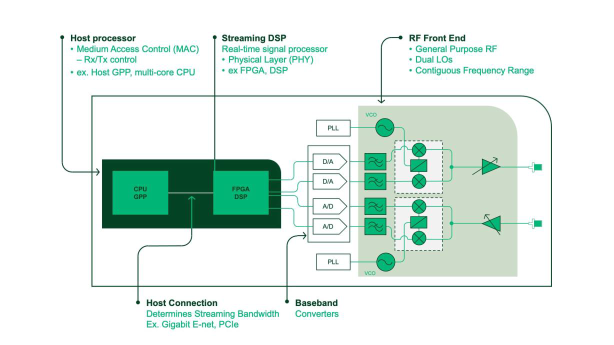
Figure 1. Typical Hardware Architecture of an SDR
1. Host Processor (e.g., multi-core CPU or general-purpose processor): responsible for Media Access Control (MAC)-layer control and application-layer code execution—the “control center” of the device;
2. Real-Time Signal Processor (e.g., FPGA or DSP): implements physical layer (PHY) algorithms and high-speed signal processing—the “computational core” of the SDR—supporting low-latency, high-bandwidth signal processing;
3. RF Front End: includes dual local oscillators (LOs), VCOs, PLLs, etc., performing frequency conversion, signal amplification, and filtering—determining the device’s frequency coverage and RF performance;
4. Baseband Converter: comprises analog-to-digital (ADC) and digital-to-analog (DAC) converters, enabling bidirectional conversion between analog RF signals and digital baseband signals—the critical “analog-digital interface”;
5. Host Interface: e.g., Gigabit Ethernet, PCIe, USB—handles data transfer between host and hardware, directly determining streaming bandwidth capability.
1.3 Generalized Performance Gradients of USRP Hardware
NI offers multiple tiers of USRP hardware models—from compact, low-cost entry-level units to high-end, multi-channel systems equipped with large FPGAs—all adhering to the aforementioned core architecture. Differences lie only in hardware configuration, performance parameters, and expansion capabilities—enabling support for varied R&D stages and application scenarios:
• Entry-Level: Based on small FPGAs—low cost and compact size—ideal for education, beginner-level R&D, and simple testing;
• Mid-to-High-End: Equipped with medium-to-large FPGAs—supports multi-channel operation and wide instantaneous bandwidth—suited for lab-based prototyping and engineering applications with moderate performance demands;
• Flagship: Features high-end RFSoC chips—supports phase coherence, ultra-wide bandwidth, and high-frequency operation—designed for demanding applications such as 6G R&D, radar research, and electronic warfare.
II. USRP Hardware Selection: Core Dimensions and Key Considerations
Hardware selection is central to USRP application and must be driven by actual use-case requirements. Six primary dimensions must be evaluated: signal parameters, SWaP-C (Size, Weight, Power, Cost), deployment form, synchronization needs, FPGA resources, and operating environment—while balancing cost against performance to avoid both unnecessary overspending on excessive capability and under-specification that fails to meet functional requirements. Below is a detailed breakdown of each selection dimension and its rationale.
2.1 Signal Parameters: Frequency Range and Instantaneous Bandwidth (Core RF Metrics)
Frequency coverage and instantaneous bandwidth are the foremost selection criteria—directly determining whether a given USRP model meets the target application’s RF requirements. Data interface throughput must also be considered to ensure efficient signal data transfer.
1. Frequency Range: USRP models span an extremely broad frequency range—from DC or 75 MHz at the low end up to multiple high-frequency tiers, accommodating full-spectrum needs from commercial communications to military RF and 6G R&D:
– Entry-Level: USRP 290x, B200mini, etc., cover up to 6 GHz—suitable for commercial communications and standard RF testing;
– Mid-to-High-End: X410 covers up to 7.2 GHz; X300 series with OBX daughterboards extends coverage to 8.4 GHz (aligned with 6G FR3 band);
– Flagship: NI Ettus USRP X420 covers up to 20 GHz—supporting FR3, Ku, and X bands—ideal for satellite communications, radar research, and advanced 6G R&D. Figure 2 shows the Ettus USRP X420, built on RFSoC, representing high-frequency, wideband SDR:
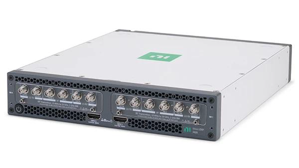
Figure 2. The Ettus USRP X420, built on RFSoC, is a high-frequency, wideband SDR with a maximum center frequency of 20 GHz.
2. Instantaneous Bandwidth: Determines the device’s ability to capture and process wideband signals. Bandwidth varies significantly across models—entry-level units typically offer ~56 MHz, whereas flagship Ettus USRP X440 achieves up to 1.6 GHz (Figure 3), meeting demanding applications like radar research and broadband spectrum monitoring;
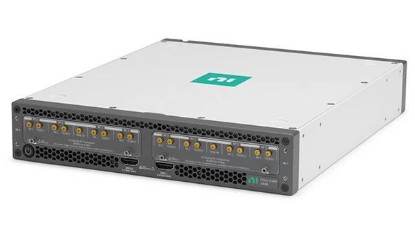
Figure 3. The Ettus USRP X440 uses a direct-sampling transceiver architecture, delivering up to 1.6 GHz per channel.
3. Data Interface Compatibility: Signal bandwidth must match the host interface’s throughput capacity. For example, USB-based USRP-290x units are bandwidth-limited and unsuitable for high-bandwidth applications, whereas the Ettus USRP X440 features dual 100 GbE interfaces—enabling high-speed transmission of massive signal datasets to satisfy the 1.6 GHz ultra-wideband requirement.
2.2 SWaP-C: Comprehensive Trade-off Among Size, Weight, Power, and Cost
SWaP-C (Size, Weight, Power, Cost) is a critical metric in engineering applications, requiring selection of a USRP model aligned with resource constraints of the intended scenario. Figure 4 shows representative low-SWaP-C USRP models:
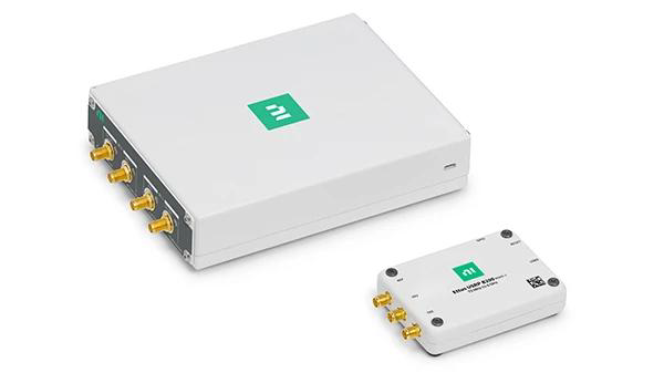
Figure 4. Low-SWaP-C USRP 2901 and USRP B200mini SDRs
1. Lab R&D Scenarios: No strict constraints on size, weight, or power—permitting selection of high-performance, larger rack-mounted units (e.g., X440, USRP 2974), prioritizing performance;
2. Embedded/Mobile Deployment Scenarios: e.g., vehicle-mounted, airborne, or soldier-portable systems—require compact, low-SWaP-C devices such as USRP B206mini or E320, optimized for mobile platforms;
3. Large-Scale Deployment Scenarios: e.g., distributed sensor networks or multi-node EW systems—demand cost-effective mid-to-high-end models (e.g., X310, N310) that balance performance and affordability.
2.3 Deployment Form: Standalone vs. Host-Connected Adaptation
USRP devices fall into two categories: host-connected and standalone. The former operates as a computer peripheral dependent on the host processor; the latter integrates an onboard embedded processor and can operate independently without centralized control. Selection depends on deployment requirements:
1. Host-Connected: Ideal for lab R&D and fixed-site testing where host infrastructure is available—lower hardware cost and leverages host computing for complex signal processing;
2. Standalone: Suited for distributed deployments, field testing, or environments lacking host support—e.g., UAV-mounted SDR or remote spectrum monitoring—featuring onboard processors for local signal processing and autonomous operation.
Table 1 lists standalone USRP models with onboard processors. Figure 5 shows the USRP 2974—a high-performance standalone SDR featuring an integrated Intel Core i7 processor:
Table 1. Standalone USRP Models with Onboard Processors
| Radio Model | Onboard Processor |
| NI USRP N320, NI USRP N321, NI USRP N310 | AMD Zynq 7100 MPSoC |
| NI USRP E320 | AMD Zynq 7045 MPSoC |
| NI Ettus USRP X410, NI Ettus USRP X420, NI Ettus USRP X440 | AMD Zynq UltraScale+™ RFSoC ZU28DR |
| NI USRP 2974 | Intel Core™ i7 6822EQ (2 GHz quad-core) |
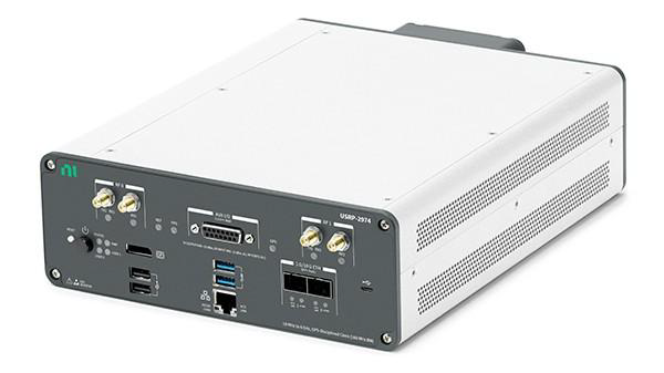
Figure 5. USRP 2974 Standalone SDR with Integrated Intel Core i7
2.4 Operating Environment: Differentiation Between Standard Labs and Harsh Environments
Most USRP models are suitable for standard laboratory environments (temperature/humidity controlled, no severe vibration). However, certain applications—such as military field deployment, industrial sites, or aerospace—impose stringent environmental requirements, necessitating ruggedized or industrial-grade USRP devices:
1. Industrial Environments: e.g., factories or outdoor sites—models such as the Ettus Research Embedded Series (Figure 6) or USRP B206mini are recommended. The former supports higher operational temperatures; the latter features an industrial-grade aluminum enclosure—meeting low-SWaP and high-reliability requirements;
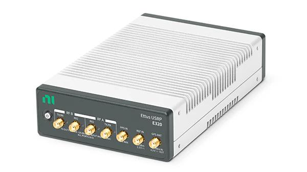
Figure 6. Embedded-Series USRP E320
2. Extreme Environments: e.g., military field operations or aerospace—NI can recommend certified ruggedization partners offering customized hardware solutions to ensure stable operation under high temperature, intense vibration, and strong electromagnetic interference.
2.5 Synchronization Requirements: From Clock Synchronization to Full Phase Coherence
Applications such as Multiple-Input Multiple-Output (MIMO), phased-array radar, distributed sensing, and multi-channel electronic warfare impose varying synchronization requirements on USRP devices. These fall into two main categories: clock synchronization and full phase coherence—requiring matching synchronization schemes and device selection:
1. Clock Synchronization: Requires only shared 10 MHz reference clock to synchronize ADC/DAC—sufficient for basic MIMO communications and simple multi-channel testing. Supported by nearly all USRP models;
2. Full Phase Coherence: Requires all channels locked to a common clock and local oscillator (LO)—essential for beamforming, phased-array radar, high-precision direction finding, and precision EW jamming. Requires specialized LO-sharing-capable models:
– Up to 4-channel receive: Ettus Research USRP X310 with dual TwinRX daughterboards enables phase-coherent operation;
– 2-channel high-frequency applications: USRP X420 supports LO sharing with phase coherence accuracy better than 1° RMS;
– Up to 8-channel operation: Ettus USRP X440 supports shared sampling clocks across 8 transmit and 8 receive channels—enabling multi-device synchronization;
– Very large-scale multi-channel systems: USRP N320/N321 (Figure 7) feature built-in LO distribution hardware—capable of up to 128×128 phase-coherent operation. Figure 8 illustrates a 32×32 phase-coherent system configuration;
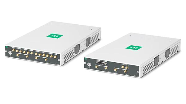
Figure 7. USRP N320 and N321 with Built-in LO Distribution Interface
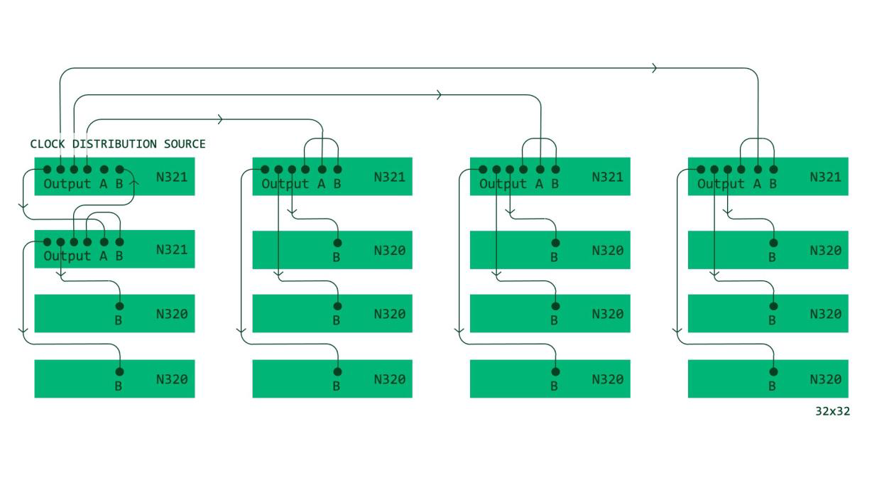
Figure 8. Multi-Channel Phase-Coherent System Using USRP N320 and N321
3. Distributed Multi-Radio Synchronization: Applicable to geographically dispersed, long-distance USRP node synchronization—e.g., wide-area spectrum monitoring or distributed EW—achievable via GPS-disciplined oscillators (GPSDO) for frequency and phase stability. Several USRP models ship with this module pre-installed (Figure 9):
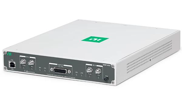
Figure 9. USRP X310 with Onboard GPS-Disciplined Oscillator
2.6 FPGA Resources: Hardware Acceleration for Embedded Signal Processing
Applications demanding wide signal bandwidth and low/deterministic latency—e.g., real-time EW, high-speed radar signal processing, and low-latency 6G communications—rely on onboard FPGA acceleration for embedded signal processing. FPGA type and resource capacity thus become critical selection criteria.
Table 2 compares FPGA-enabled USRP models. Figure 10 compares FPGA resources across NI FPGA products. Primary selection criteria depend on the application’s signal processing requirements:
Table 2. Comparison of FPGA-Enabled USRP Models
| USRP Model | Onboard FPGA |
| USRP N320, USRP N321, USRP N310 | AMD Zynq 7100 MPSoC |
| USRP E320 | AMD Zynq 7045 MPSoC |
| Ettus USRP X410, USRP X420, USRP X440 | AMD Zynq UltraScale+ RFSoC ZU28DR |
| USRP 2974, USRP X310 | AMD Kintex 7 410T |
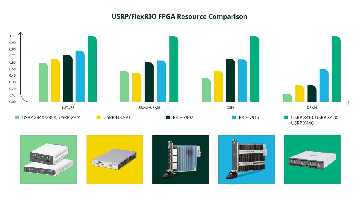
Figure 10. Comparison of FPGA Resources Across NI FPGA Products
1. No Embedded Processing Required: e.g., basic spectrum monitoring or entry-level comms testing—select entry-level models with small FPGAs (e.g., USRP B206mini), which provide no user-code development space but fulfill basic needs;
2. Moderate Embedded Processing Needs: e.g., standard radar signal processing or civilian comms algorithm validation—choose models with AMD Kintex 7 410T (e.g., USRP 2974, X310), offering balanced FPGA resources for standard custom algorithms;
3. High-Performance Embedded Processing Needs: e.g., real-time EW jamming, high-speed 6G algorithms, or phased-array radar beamforming—opt for flagship models with AMD Zynq UltraScale+ RFSoC (e.g., X410, X420, X440), integrating soft-decision forward error correction (SD-FEC), multiple Arm processors, and integrated ADC/DAC—delivering abundant FPGA resources for developing and deploying complex custom algorithms.
III. USRP Software Development: Diverse Toolchains and Compatibility
Programmability is the core advantage of SDR. As a highly open SDR platform, USRP supports two major programming paradigms—host-side programming and FPGA programming—with diverse toolchains tailored to different engineers’ development preferences, technical backgrounds, and application requirements. From graphical programming to open-source code development, and from domain-specific software to general-purpose frameworks, USRP enables end-to-end development coverage. Figure 11 illustrates the general software and FPGA development toolflow available for USRP—the central reference for software selection:
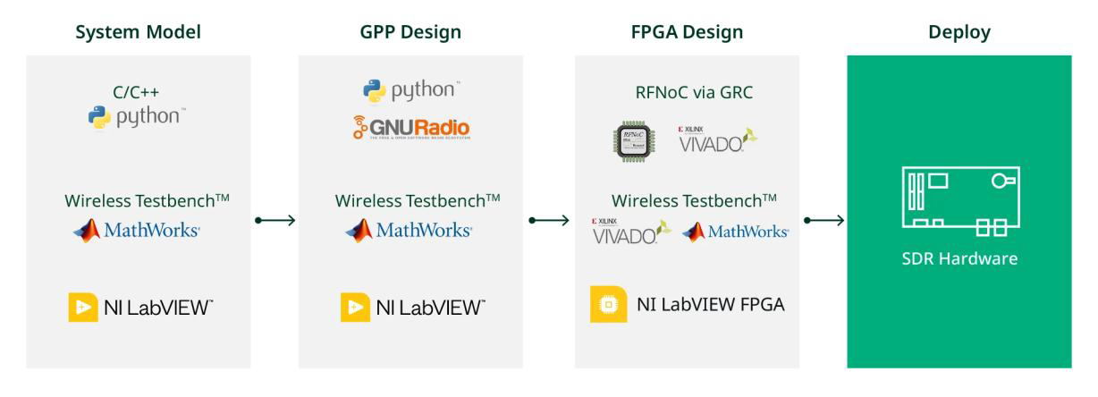
Figure 11. SDR Software and FPGA Options
3.1 Host Programming: Multi-Tool Compatibility Balancing Professional and Open-Source Use
Host programming primarily handles application-layer logic and signal processing algorithm design—performing high-level signal processing, data analysis, and device control. USRP supports four mainstream development tools, each with distinct characteristics and ideal use cases—allowing engineers to select based on their technical background and application needs:
1. NI LabVIEW
– Characteristics: Graphical dataflow programming environment purpose-built for communications and RF algorithm development. Uses NI-USRP drivers for hardware configuration and baseband I/Q data I/O—no low-level coding required, enabling rapid development;
– Target Applications: Rapid prototyping, lab R&D, engineers without open-source coding experience;
– Notes: Primarily Windows-based; limited support for some Ettus Research-branded USRP models;
– Development Example: Figure 12 shows the block diagram of a LabVIEW screen using the NI-USRP driver API.
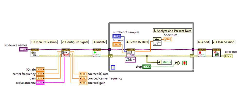
Figure 12. Block Diagram of a LabVIEW Screen Using the NI-USRP Driver API
2. Open-Source Toolchain (UHD + GNU Radio / Redhawk)
– Characteristics: All USRP models support the open-source USRP Hardware Driver (UHD), compatible with C/C++ and Python programming. Integrates seamlessly with open-source SDR frameworks like GNU Radio and Redhawk—offering high flexibility, cross-platform support, and access to rich community IP libraries;
– Target Applications: Open-source community development, highly customized engineering applications, engineers with programming experience;
– Development Example: Figure 13 shows the GNU Radio flowchart.
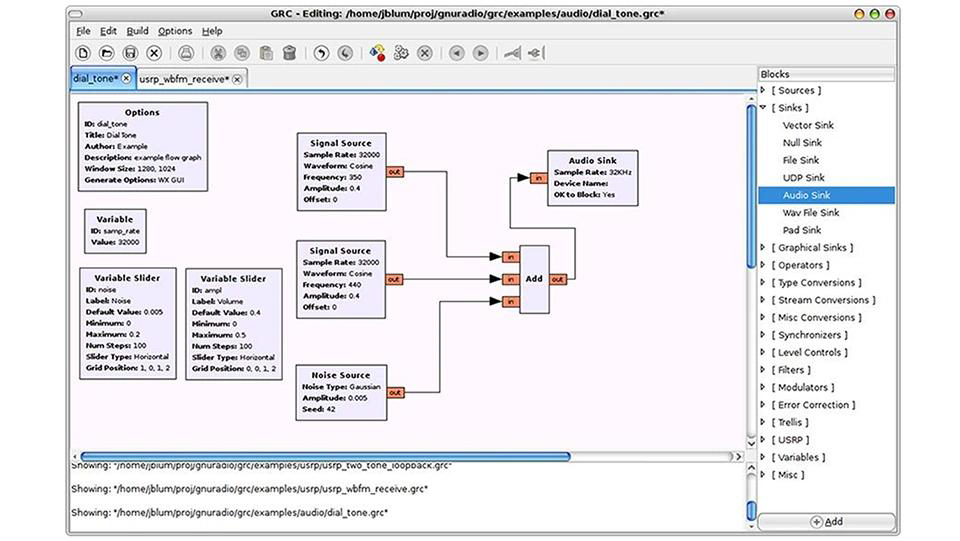
Figure 13. GNU Radio Flowchart
3. MathWorks MATLAB/Simulink
– Characteristics: Paired with toolboxes such as Wireless Testbench™ and Communications Toolbox™, enabling radio-in-the-loop testing, broadband wireless system design, and spectrum monitoring. Supports FPGA integration of custom IP via HDL Coder;
– Target Applications: Algorithm simulation, radar/communications system design, prototype validation integrated with MATLAB simulation workflows;
– Notes: Toolbox support varies by USRP model—e.g., Wireless Testbench supports N3xx, X3xx, and X4xx series.
4. General Industrial-Grade Tools: Compatible with universal programming languages (C/C++, Python), supporting enterprise-grade customization and production deployment.
3.2 FPGA Programming: Two Core Hardware-Acceleration Approaches
FPGA programming focuses on hardware-accelerated, low-latency, high-bandwidth signal processing (e.g., beamforming, real-time filtering, modulation/demodulation). USRP provides two standardized, high-abstraction FPGA programming approaches—significantly lowering traditional FPGA development complexity and eliminating the need to build board-support packages from scratch:
1. LabVIEW FPGA
– Characteristics: An add-on to LabVIEW enabling graphical FPGA programming. Abstracts hardware and data interfaces, simplifies register configuration and data movement, and unifies host and FPGA development within one toolchain. Supports importing legacy VHDL/Verilog IP via Component-Level IP (CLIP) nodes—and exporting AMD Vivado projects for expert users;
– Target Applications: Engineers familiar with LabVIEW, rapid FPGA prototyping, reuse of legacy IP;
– Notes: Windows-only; limited support for some Ettus Research devices;
– Development Example: Figure 14 shows a simple LabVIEW FPGA block diagram.
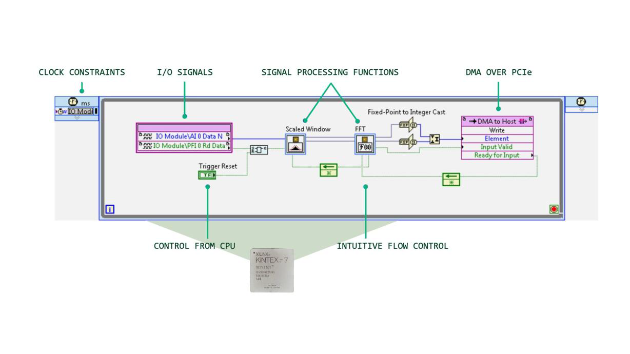
Figure 14. Simple LabVIEW FPGA Block Diagram
2. Radio Frequency Network-on-Chip (RFNoC) Framework
– Characteristics: The preferred FPGA programming solution for open-source USRP users. Acts as both a data interface and command abstraction layer—enabling flexible plug-and-play of IP blocks via crossbar switch matrix interfaces—eliminating the need to rebuild entire FPGA bitstreams. Deeply integrated with GNU Radio;
– Target Applications: Open-source community development, highly customized FPGA algorithm development, distributed multi-node SDR systems;
– Supported Models: USRP X300 series, E300 series, N300 series, X400 series;
– Development Example: Figure 15 shows the conceptual block diagram of RFNoC integrated with GNU Radio.
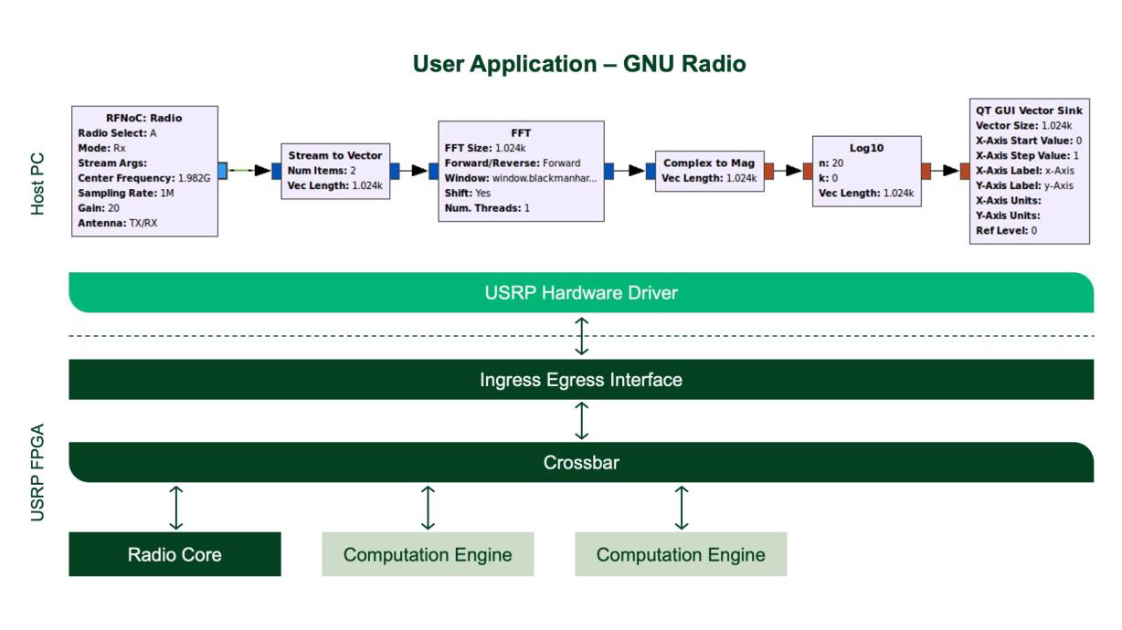
Figure 15. Conceptual Block Diagram of RFNoC Integrated with GNU Radio
IV. USRP Full Model Matrix: Classification, Characteristics, and Software Support
NI classifies USRP models into four categories based on performance, deployment form, and SWaP-C. Each category exhibits distinct technical characteristics suited to specific application scenarios. Table 3 presents the complete USRP hardware and supported software matrix—clearly indicating core RF parameters, channel count, and software compatibility—serving as the primary reference for rapid, informed selection:
Table 3. USRP Hardware and Supported Software


4.1 Standalone, FPGA-Supported, High-Performance Models
• Representative Models: USRP X440, X420, X410, N320/N321, 2974;
• Core Characteristics: Equipped with high-end RFSoC/MPSoC—supporting multi-channel operation, wide instantaneous bandwidth, and phase coherence—with powerful onboard processors enabling standalone deployment;
• Software Support: Compatible with UHD, GNU Radio, and MATLAB; LabVIEW support varies by model;
• Target Applications: Advanced 6G R&D, radar research, electronic warfare, satellite communications, and large-scale multi-channel systems.
4.2 Host-Connected, FPGA-Supported, High-Performance Models
• Representative Models: USRP 2944/2945/2954/2955, X310 series (with UBX/TwinRX/OBX daughterboards);
• Core Characteristics: Leverages host computing for high-performance processing; supports FPGA development; frequency coverage up to 6 GHz / 8.4 GHz—suitable for medium-scale multi-channel systems;
• Software Support: Fully supports LabVIEW, UHD, GNU Radio, and MATLAB;
• Target Applications: Lab-grade communications/radar prototyping, broadband spectrum monitoring, and medium-performance EW testing.
4.3 Low-SWaP, Standalone Embedded Models
• Representative Model: USRP E320;
• Core Characteristics: Compact size and low power consumption; embedded processor enables standalone deployment—ideal for mobile platforms;
• Software Support: Supports UHD and GNU Radio; does not support LabVIEW;
• Target Applications: Vehicle-/airborne-mounted SDR, distributed sensing, soldier-portable RF equipment.
4.4 Low-SWaP, Low-Cost, USB-Connected Models
• Representative Models: USRP B206mini, 2900/2901;
• Core Characteristics: Low cost and compact size; connects to host via USB—performance sufficient for basic applications;
• Software Support: Supports LabVIEW, UHD, and GNU Radio; does not support FPGA development;
• Target Applications: Entry-level R&D, education, basic spectrum monitoring, and low-cost miniaturized testing.
V. USRP Core Selection Principles and Cross-Industry Application Value
5.1 Core Selection Principles
Based on the comprehensive hardware and software development analysis above, USRP selection must follow the core principles of **“demand-driven, parameter-matched, cost-balanced, and extensibility-compatible”**, implemented in four steps to ensure scientific rigor and practical implementation:
1. Clarify Core Application Requirements: Define the usage scenario (lab/field/embedded), RF specifications (frequency/bandwidth), critical performance needs (synchronization/low latency/FPGA acceleration), and environmental constraints (standard/harsh);
2. Match Core Hardware Parameters: Filter candidate models based on required frequency coverage, bandwidth, synchronization capability, FPGA resources, and SWaP-C;
3. Confirm Software Development Compatibility: Verify toolchain support (graphical vs. open-source programming) based on team expertise—avoiding incompatible development environments;
4. Balance Cost and Scalability: Select the most cost-effective model satisfying current requirements—while considering future scalability (e.g., multi-channel upgrades or high-frequency expansion) to reserve hardware headroom.
5.2 Cross-Domain Application Value
As a general-purpose SDR platform, USRP delivers broad application value across sectors—leveraging its rich hardware matrix, diverse development toolchains, and high flexibility—as a universal RF tool for both civilian research and military R&D:
1. Civilian Applications: 6G/5G-A R&D, civilian radar design, wireless communications testing, spectrum monitoring, UAV communications and countermeasures—accelerating innovation and prototyping in civilian RF technologies;
2. Military Applications: Electronic warfare (spectrum reconnaissance, real-time jamming), RF module development for missile seekers, phased-array radar prototyping, distributed military sensor networks, and soldier-/vehicle-mounted RF equipment—its low SWaP, high flexibility, and phase-coherence capabilities perfectly align with military RF R&D and test requirements;
3. Academic & Educational Applications: Teaching and research in university programs covering RF communications, radar, and electronic information—lowering the learning and development barrier for SDR technology and cultivating next-generation RF talent.
VI. Dayao Technology Products vs. Mainstream USRP Hardware and Software: Comparative Analysis
As an enterprise deeply engaged in the Software-Defined Radio (SDR) domain, Dayao Technology develops a series of general-purpose SDR devices grounded in market demand and technological innovation. Its core performance metrics align with mainstream USRP offerings, while incorporating functional optimizations and performance enhancements tailored to real-world applications—fully supporting replacement and upgrade requirements across all USRP application scenarios.
To help readers quickly compare core differences between Dayao Technology products and mainstream USRP models—and precisely match selection needs while clearly understanding Dayao Technology’s competitive advantages—the following section presents a side-by-side comparison table, mapping Dayao Technology products to corresponding USRP models—providing more intuitive and targeted references for selection decisions.
Table 4. Comparative Table of Dayao Technology Products and Mainstream USRP Hardware and Software
| USRP Model | Dayao Technology Model | Optimization Highlights |
| USRP B210 | DY-RF210H | Functionally aligned with USRP B210, with expanded functionality and performance. Achieves 1 MHz–6 GHz frequency coverage via external up/down-conversion and filter banks. Optimized software drivers enable fast frequency hopping. Pre-selection filter banks in both TX and RX RF front ends improve frequency selectivity, enhancing harmonic and spurious suppression—resulting in improved receiver performance versus the original B210. |
| USRP X310 | DY-RF310 | Functionally aligned with USRP X310, with extended performance. Optimized driver design enables configurable master clock rates (original supports only 200 MHz and 184.32 MHz), allowing precise arbitrary sample rate configuration. |
| USRP E320 | DY-RF320G | Functionally aligned with USRP E320, with full domestic substitution—designed using Fudan Microelectronics FMAL45T900 and Beiwei Electronics MTX9361 chips. |
| USRP N321 | DY-RF321 | Functionally aligned with USRP N321, with expanded functionality and performance—covering 1 MHz–6 GHz (N321 covers 30 MHz–6 GHz). |
| DY-RF325 | Covers 1 MHz–6 GHz with maximum instantaneous bandwidth of 500 MHz. | |
| GNU Radio | Tianwen Electromagnetic Signal Simulation, Development, and Control System | Aligned with MATLAB/LabVIEW, built on a browser-server (B/S) architecture, and natively compatible with the GNU Radio kernel. Offers three-tier simulation capabilities—algorithms, equipment, and scenarios—enabling full-cycle electromagnetic signal simulation and control design. Figure 16. Tianwen Electromagnetic Signal Simulation and Development System |
Disclaimer: All technical parameters and model information in this white paper are sourced from the official content published by NI on its website on February 24, 2026. Hardware specifications and software support may change with product updates—please refer to the latest official information on the NI website for authoritative details.