As Alice walked out of the theater, she still clutched the signal flow diagram in her hand—Antenna → RF Front-End → ADC → DDC → Baseband Processing → DUC → DAC → RF Front-End → Antenna. She glanced down as she walked, her gaze lingering for a long time on the labels “DDC” and “DUC.”
“This is my brother FPGA’s domain,” she murmured to herself. “The Digital Frequency Conversion Factory.”
She looked up. Ahead stood a massive factory. Its chimneys did not emit black smoke—but constantly shifting frequency spectra: some high, some low, some slowly gliding, others rapidly hopping. The factory walls were made of translucent glass; from outside, she could see countless conveyor belts running inside—but instead of parts, they carried signals. Those signals entered one end as dense, high-speed oscillating needle-like waveforms, and exited the other end as smooth, slowly undulating baseband waveforms.
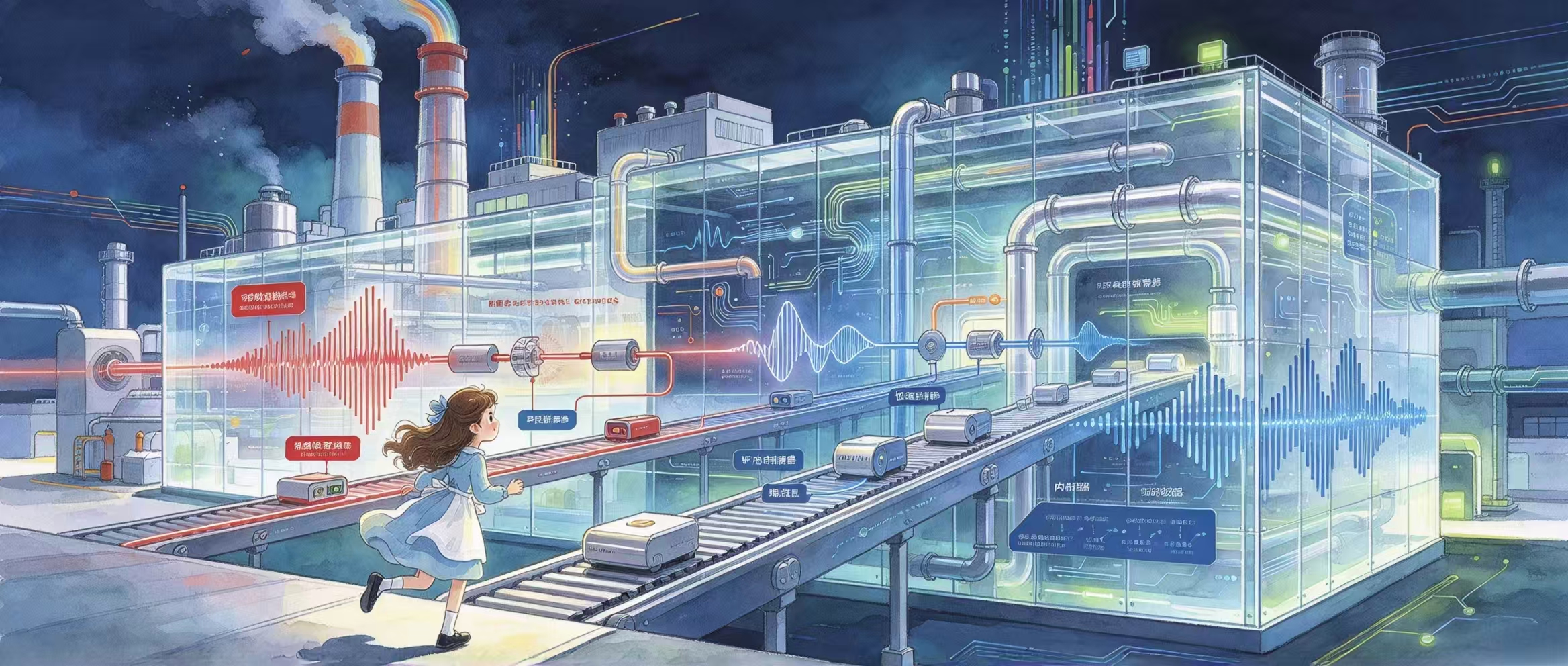
A sign hung above the factory gate:
"Digital Frequency Conversion Factory—Where different ‘languages’ are translated."
Alice pushed open the door and stepped inside. The interior was quieter than she had imagined—conveyor belts ran silently, and thousands upon thousands of signals flowed noiselessly through transparent pipes. The only sound came from a loudspeaker mounted high overhead:
"Receive path—DDC, Digital Downconversion, currently translating: High-frequency language → Low-frequency language."
"Transmit path—DUC, Digital Upconversion, currently performing reverse translation: Low-frequency language → High-frequency language."
Alice walked forward along the main aisle. The factory was divided into two zones—on the left read “DDC—Receive Path,” and on the right, “DUC—Transmit Path,” each with long conveyor belts. At the start of each belt stood a figure—broad-shouldered, wearing red workwear adorned with logic unit patterns, arms crossed firmly across his chest, as if waiting for her.
"You’re here." FPGA said. "I knew you’d be the first to come."
"Weren’t you performing in the theater?"
FPGA chuckled—a sound like ten thousand switches snapping shut simultaneously: "The theater was just an introduction. This is where the real work happens. Come—I’ll show you how DDC and DUC actually run."
I. Receive Path—DDC: Bringing High Frequencies ‘Down’
FPGA led Alice to the start of the conveyor belt. A signal stream flowed along it—high-frequency, densely oscillating needle-like waveforms, so fast that individual oscillations were nearly invisible to the naked eye.
"This is the high-frequency signal coming from the antenna," FPGA explained. "It has already passed through the RF front-end for amplification, filtering, and analog frequency conversion—and then been digitized by the ADC. Now it flows continuously from the ADC output straight into my hands. It’s extremely fast—tens to hundreds of mega-samples per second—so fast that a DSP would get dizzy just looking at it, and a CPU would crash instantly."
"So the first thing we do is—"Slow it down. ”
He pointed to three workstations arranged sequentially along the conveyor belt:
Workstation ①: Mixer.Here, the high-frequency digital signal on the conveyor belt 'meets' a locally generated digital frequency—their difference yields a lower-frequency signal.
“Mixing—subtracting the high-frequency signal and a local oscillator frequency to produce an intermediate frequency (IF). Like listening to the difference between two spoken languages simultaneously."
Workstation ②: Filter.After mixing, the signal passes through a precision sieve, allowing only the designated frequency band to pass while blocking all others.
“Filtering—removing spurious frequencies generated during mixing, retaining only the desired band."
Workstation ③: Decimator.As the signal passes through here, the conveyor belt suddenly slows—only 10 out of every 100 samples are retained, reducing data volume to one-tenth of its original size.
“Decimation—once the signal frequency drops, fewer samples are needed. We retain just enough samples to preserve full signal information, enabling downstream DSP and CPU processing."
After passing through all three stations, Alice saw the output signal at the end of the conveyor belt—it was no longer the high-frequency needle-like waveform, but a smooth, slowly undulatingbaseband signal.
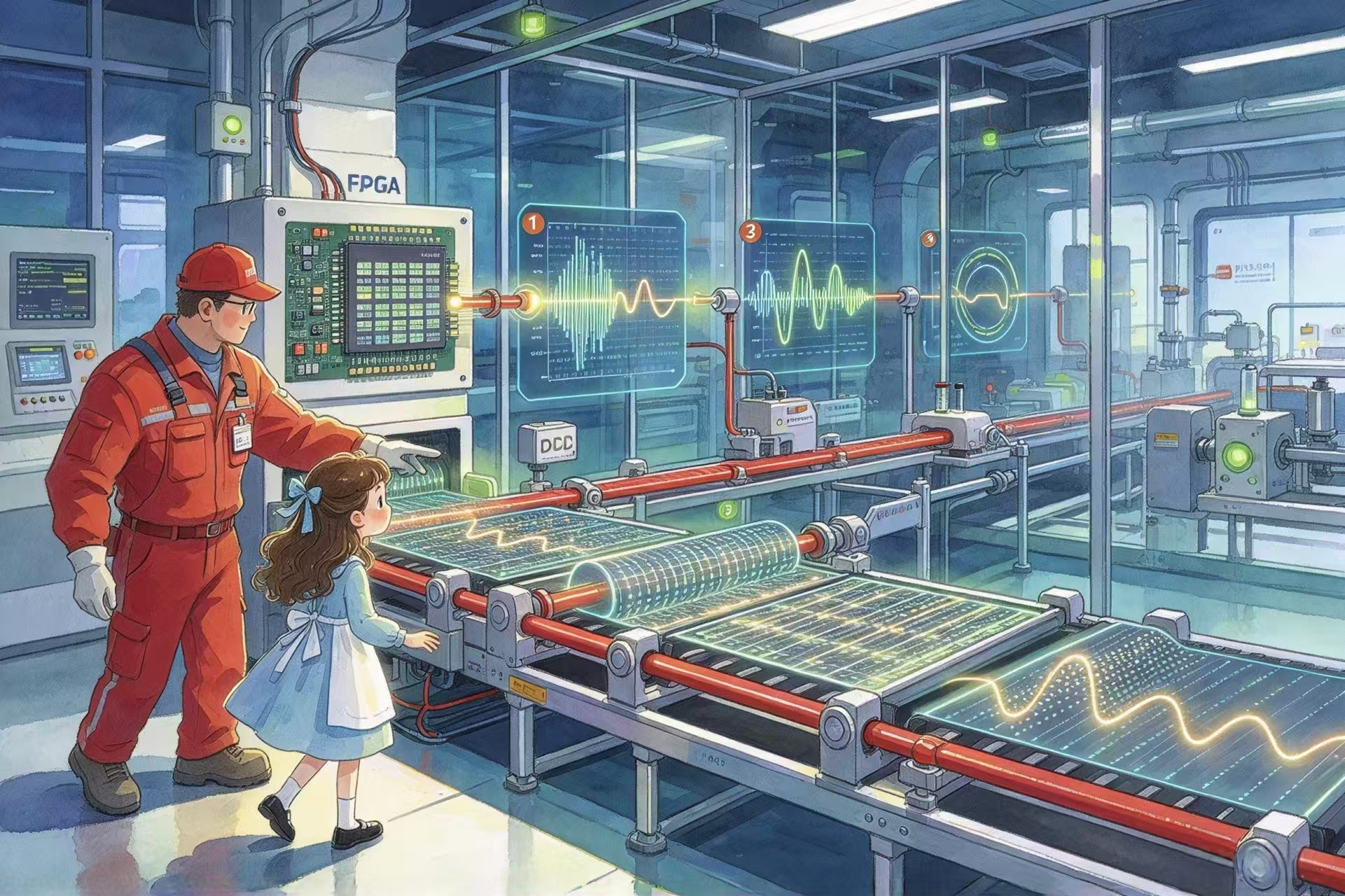
"High-frequency language" → "Intermediate-frequency language" → "Baseband language." It had been 'translated' twice, its speed reduced to roughly one-fortieth of the original—now easy to understand and process.
"This isDigital Downconversion—DDC." FPGA said. "Translating a high-frequency, impossibly fast language into a low-frequency, manageable one. The digital signal from the ADC undergoes its first—and most critical—speed reduction right here in my hands."
II. Transmit Path—DUC: Lifting Low Frequencies ‘Up’
"Now let’s look at the other side." FPGA walked to the start of the conveyor belt on the factory’s right side.
The signal at this starting point was completely different from what she’d seen earlier—it was a slowly flowing, widely spaced baseband waveform, the processed baseband signal ready for transmission after being handled by the DSP and CPU.
"This is the baseband signal handed over to me by the DSP—perhaps your voice or the data you want to send. It’s very slow, very low in frequency—impossible to transmit directly via antenna. The lower the frequency, the longer the required antenna—transmitting baseband directly would demand an antenna tens of meters long."
"So we need to reverse the process: translate the ‘slow language’ into a ‘fast language.’"
The three workstations on the right side mirrored those on the left—but in precisely reversed order:
Workstation ①: Interpolator.The slow baseband signal passes through an ‘accelerator,’ inserting additional data points between existing ones—multiplying the data volume.
“Interpolation—increasing sample density to provide sufficient resolution for frequency up-conversion."
Workstation ②: Filter.The signal passes through another set of sieves, removing ‘image frequencies’ introduced during interpolation, leaving only a clean, smooth signal.
"After interpolation, we must ‘trim the edges’—otherwise unwanted spurious components will contaminate the signal."
Workstation ③: Mixer.The signal ‘meets’ a locally generated high-frequency digital carrier—their sum produces a high-frequency output signal.
“Mixing—lifting the low-frequency signal onto the carrier. Now it ‘rides’ the carrier wave, elevated to the RF band—ready for transmission via antenna."
After passing through all three stations, the output signal at the conveyor belt’s end reverted to a high-frequency, densely oscillating waveform—nearly identical to the one Alice had seen at the start of the DDC section.
"Baseband low-frequency language" → "Intermediate-frequency language" → "RF high-frequency language." It had been ‘reverse-translated’ twice, its speed increased dozens of times—ready to be converted back to analog by the DAC and transmitted via the RF front-end.
"This isDigital Upconversion—DUC." FPGA said. "Translating a low-frequency baseband signal into a high-frequency RF signal—so it can fly out through the antenna."
III. Inverse Relationship
Alice stood between the two conveyor belts—DDC receive line on the left, DUC transmit line on the right. She placed the two flow diagrams side-by-side:
• DDC (Receive) : Mixer → Filter → Decimator
• DUC (Transmit) : Interpolator → Filter → Mixer
"They’re almost exact inverses?" Alice asked.
"Absolutely correct!" FPGA’s voice carried clear satisfaction. "DDC performs subtraction—frequency drops progressively, data is decimated stepwise. DUC performs addition—frequency rises progressively, data is interpolated increasingly. Decimation and interpolation are inverse operations. Mixing appears in both directions—but in reception it’s subtraction, while in transmission it’s addition."
He pointed to two parallel flow diagrams displayed on the control panel:
"The inverse of DDC is DUC.In the SDR world, if you can receive, you can transmit—provided you reverse the process."
"And all of this," he patted his chest, "happens within my domain. Mixing, filtering, decimation, interpolation—these operations must handle hundreds of millions of data streams simultaneously, executing billions of calculations per second—no waiting, no queuing, no ‘one-at-a-time’ processing. Only I possess ten thousand hands working concurrently."
"My brother DSP calculates precisely—but cannot handle such massive parallelism. My younger brother CPU manages broadly—but lacks the speed. Digital frequency conversion is inherently *my* domain."
IV. Position of Frequency Conversion in the Signal Flow
FPGA guided Alice to the factory’s control center. On the wall hung a large "Frequency Translation Map"—identical to the signal flow diagram she’d seen in the corridor, but now with the DDC and DUC sections highlighted in red.
"Look here," FPGA pointed at the map, "across the entire signal chain, much of the digital processing between ADC and DAC involves frequency manipulation—slowing down, speeding up, mixing, filtering."
"My position lies exactly here—from ADC output to baseband input, and from baseband output to DAC input.All digital frequency conversion tasks are performed by me. Then I hand off the processed baseband signal to the DSP—and receive the transmit baseband signal from the DSP."
"What about the DSP?" Alice asked.
"He stands in the baseband zone, handling modulation/demodulation, coding/decoding, equalization—tasks demanding high computational precision. But he doesn’t touch frequency conversion; it’s too coarse and heavy—he can’t handle it."
"And the CPU?"
"He resides at the very top of the entire map—not on any conveyor belt—but orchestrates how each belt operates: setting frequency parameters, filter configurations, sampling rates—all commands originate from him."
Alice studied the color-coded division of labor on the map and finally grasped how the entire signal flow operated.
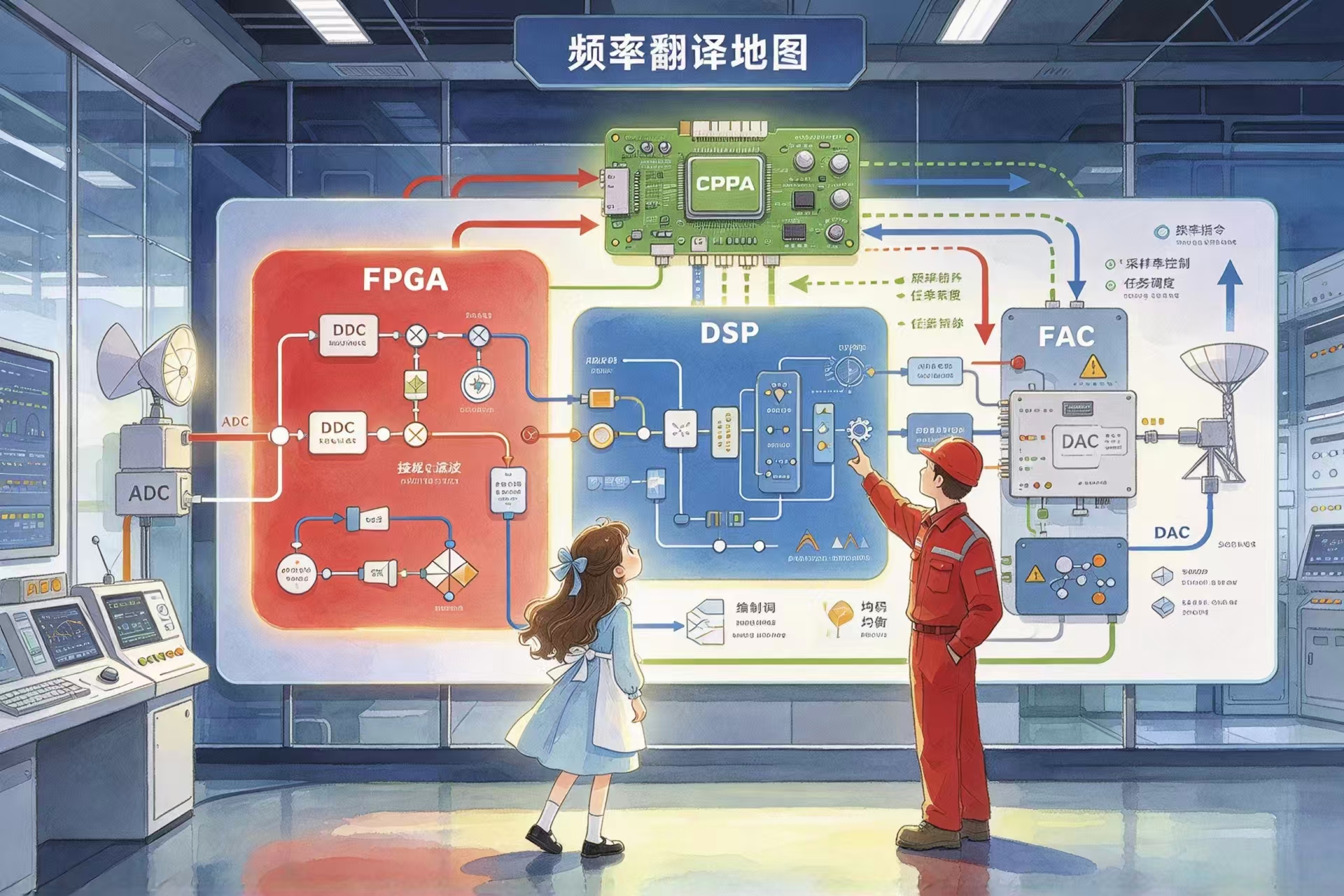
"So the complete signal path is—Antenna → RF Front-End → ADC → FPGA (performing DDC) → DSP (performing Baseband Processing) → FPGA (performing DUC) → DAC → RF Front-End → Antenna Transmission。”
"FPGA performs two critical roles—one downconverting during reception, another upconverting during transmission. DSP executes one round of precise computation in between. CPU oversees everything from above."
"Exactly right." FPGA slid his hands into the pockets of his red workwear. "That’s the full story of the SDR digital domain—heavy lifting belongs to me, precision computation to DSP, and system management to CPU."
He pointed toward the factory exit: "Next stop, you’ll see me—and my brothers—in different physical forms across various circuit boards. On some boards, I occupy only a small room; on others, an entire floor. And on one platform—I share a single room with my younger brother CPU."
"Next stop?"
“The Hardware Expo." FPGA said, "There you’ll see how the three brothers divide responsibilities across different platforms."
V. Factory Exit
As Alice walked out of the factory, dusk was approaching. Inside the translucent walls, conveyor belts continued running, signals kept flowing, and mixers, filters, decimators, and interpolators persisted in executing their translation instructions at their respective stations.
Beneath the sign above the factory gate, an additional line of text had appeared—as if freshly added just as she departed:
"Not a factory that *creates* signals—but one that *translates* them."
"—Translator-in-Chief: Brother FPGA."
Alice turned back and saw the broad-shouldered red figure still standing at the factory entrance. His ten thousand hands were now folded away—but behind him, the conveyor belts continued running ceaselessly: translating high frequencies to low, low frequencies to high—day after day, frequency in, frequency out. That was why the Digital Frequency Conversion Factory never stopped.
She turned and walked toward the next destination.
In the distance, the silhouette of a massive exhibition hall emerged. Beneath its transparent glass dome, lights illuminated countless booths and circuit boards. She began imagining how the three brothers would appear on those displays.
(To be continued. Next chapter: The Hardware Expo—Alice will enter the SDR Hardware Expo, ranging from the $10 RTL-SDR to the $10,000+ USRP, from the bright-yellow HackRF to the self-contained Zynq platform. On each board, she’ll search for Brother FPGA—watching him evolve from a ‘small room’ to an ‘entire floor.’)
[Chapter Five Key Concepts Recap]
| SDR Concept | Fairy-Tale Personification |
| Digital Downconversion (DDC)—Receive Path | High Frequency → Intermediate Frequency → Baseband: Signals become progressively slower |
| Digital Upconversion (DUC)—Transmit Path | Baseband → Intermediate Frequency → RF: Signals become progressively faster |
| Mixing (Receive) | Subtracting high-frequency signal and local oscillator frequency → Output IF frequency |
| Mixing (Transmit) | Adding baseband frequency and local oscillator frequency → Output RF frequency |
| Filtering | Removing unwanted frequency bands—retaining only the desired portion |
| Decimation | Receive path: Reducing data points to lower data rate |
| Interpolation | Transmit path: Increasing data points to raise data rate |
| Mirror Relationship Between DDC and DUC | Reversing the receive flow diagram yields the transmit flow diagram—same operations, opposite direction |
| Relationship Between DDC/DUC and FPGA | Digital frequency conversion demands high-speed, massively parallel processing of enormous data streams—thus typically implemented in FPGA. FPGA is the ‘home-field player’ of the frequency conversion factory. |
| Division of Labor Among the Three Brothers in the Signal Flow | FPGA handles DDC/DUC (heavy lifting), DSP handles baseband processing (precision work), CPU handles control and management (orchestration) |
Preview of Next Chapter
The Hardware Expo—Alice will enter the SDR Hardware Expo, ranging from the $10 RTL-SDR to the $10,000+ USRP, from the bright-yellow HackRF to the self-contained Zynq platform. She’ll seek out the three brothers on each board—RTL-SDR contains no FPGA; HackRF features a simplified CPLD; USRP houses a full FPGA; and Zynq integrates FPGA and CPU into a single chip.
This article is original content. Please credit the author, official WeChat account, and official website (https://www.dyaotech.com), and do not modify or commercialize without authorization. Violators will be held legally accountable!